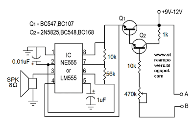
This is a water sensor /rain alarm circuit diagram; it can be used on motorcycle, car or other device that we want to protect from water, rain.
This is a simple water sensor/rain alarm circuit that makes an alarm when water/rain falls on its sensor. This circuit is based on NE555/LM555 IC and two transistors (Q1&Q2). For transistor Q1- BC547 or BC107 and for Q2- 2N825,BC548 or BC168 can be used in the circuit.
This rain detector circuit can be supplied from voltage source of +9V-12V DC. The resistor 470K ohm is a POT/Variable resistor; it is used to adjust the sensitivity of water/rain sensor. Use a 8 ohm,0.5w-1W speaker to hearing better alarm. Less than 8 ohm speaker could be harmful for the IC 555.
Circuit Diagram of Water Sensor
We can make the water sensor as shown in the image (Fig-1) using aluminum conductor like a naked wire . Here can be used other conductor but we suggesting to use aluminum.


