Simple 9-V Battery Replacement


This circuit was originally designed to power a motorcycle intercom from the vehicle supply system. This type of intercom, which is used for communication between driver and passenger, generally requires quite a bit of power. In order to improve intelligibility there is often elaborate filtering and a compander is sometimes used as well. The disadvantage is that a battery doesn’t last very long. You could use rechargeable batteries, of course, but that is often rather laborious. It seems much more obvious to use the motorcycle power supply instead. 

9-V Battery Replacement Circuit Diagram


9-V Battery Replacement Circuit Diagram


A 9-V converter for such an application has to meet a few special requirements. For one, it has to prevent interference from, for example, the ignition system reaching the attached circuit. It is also preferable that the entire circuit fits in the 9-V battery compartment. This circuit meets these requirements quite successfully and the design has nonetheless remained fairly simple. In the schematic we can recognise a filter, followed by a voltage regulator and a voltage indicator. D1, which protects the circuit against reverse polarity, is followed by an LC and an RC filter (C3/L1/L2/C1/R1/C2). This filter excludes various disturbances from the motorcycle power system. Moreover, the design with the 78L08 and D3 ensures that the voltage regulator is operating in the linear region. The nominal sys-tem voltage of 14 V can some-times sag to about 12 V when heavy loads such as the lights are switched on. 

Although the circuit is obviously suitable for all kinds of applications, we would like to mention that it has been extensively tested on a Yamaha TRX850. These tests show that the converter functions very well and that the interference suppression is excellent.

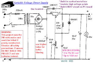
Simple 1A Variable Regulated Power Supply Circuit Diagram


This is the simple 1A Variable Regulated Power Supply Circuit Diagram. A power supply unit is a must for every electrical and electronic work bench and it’s available in a variety of shapes and sizes in the market and also in the form of schematics to us.

 Simple 1A Variable Regulated Power Supply Circuit Diagram


Simple 1A Variable Regulated Power Supply Circuit Diagram

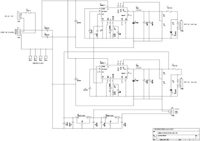
15V - 28V 4A Transmitter Power Supply Circuit Diagram


This is the simple 15V - 28V 4A Transmitter Power Supply Circuit Diagram. Power supply used for professional FM broadcasting transmitter.


15V - 28V 4A Transmitter Power Supply Circuit Diagram

15V - 28V 4A Transmitter Power Supply Circuit Diagram


Sourced by: electronics-diy

Simple 12V to 9V with a LM317 Circuit Diagram


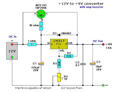
This little circuit uses a LM317 variable voltage regulator to adjust the input voltage down to +9 volt, or whatever else you need. Just a solid basic circuit without bells and whistles. You can do with a 10uF capacitor for C1 if your battery is close to this circuit. If it is located more than 3 feet increase the value to 100uF or above. Without a coolrib it can easily handle 500mA. If you need more, or the maximum current (1.5A), then a good coolrib is required.

 Simple 12V to 9V with a LM317 Circuit Diagram

Simple 12V to 9V with a LM317 Circuit Diagram


Trimmer potentiometer R3 will vary the output voltage. Ceramic capacitor C2 improves frequency/transient response. Can be omitted if not needed for your application. If you want extra protection in case the adjust pin is short circuited, add an extra 1N4001 diode over the input and the output. Cathode to input. But normally only used if the output is way over 25V.

Simple 12V to 9V with a LM317 Circuit Diagram 1

Simple 12V to 9V with a LM317 Circuit Diagram


R1 and R3 determine the output voltage. You can adapt them for your own needs and applications.
Use the following formula: (((R1+R3)/R2)+1)*1.25=V-out which comes to: (((560+1000)/220)+1)*1.25 = 10.11V (assuming V-in is 12V).


Or vice-versa: ((V-out/1.25)-1)*R2=R1+R3 which comes to: ((9/1.25)-1)*220=1364. For 1364, you can make R1=560 and R3=1K, which will give plenty of play.

After dozens of emails I have included the above circuit. The parts with the red 'X' are added and act to boost the amperage. The NTE393 transistor can handle 25A with a sufficient coolrib.

Other power transistors, such as the TIP2955, or similar can be used also. The power transistor is used to boost the extra needed current above the maximum allowable current provided via the regulator. Current up to 1500mA(1.5A) will flow through the regulator, anything above that makes the regulator conduct and adding the extra needed current to the output load.

It is no problem stacking power transistors for even more current. Both regulator and power transistor must be mounted on an adequate heatsink, and if you intend to use lots of amps a fan would be nice too.


Sourced By :  Copyright © 2003 - Tony van Roon