Elec +30V power supply with +5V Circuit Diagram


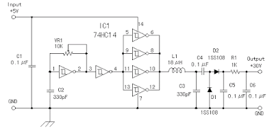
This is the Elec +30V power supply with +5V Circuit Diagram.  I made the power supply which makes about +30V with +5V power supply. The direct current is changed into the alternating current by the oscillator which used the schmitt trigger inverter which has the hysteresis characteristic and the resonance circuit. 

 Elec +30V power supply with +5V Circuit Diagram


Elec +30V power supply with +5V Circuit Diagram


The high DC voltage (+50V) is made with the alternating voltage using the voltage amplification rectification circuit. The output voltage of this circuit changes mainly when the load changes. So, this power supply can be used only as the power supply of the circuit that the load is constant or the circuit which doesn't have a problem even if the voltage changes.

Simple +9V and -9V from one Battery


The MAX1044 is a charge pump converter - it uses a capacitor as a "bucket" to pump charge from one place to another. In this case, the 1044 connects the + terminal of C1 to +9V from the battery and its negative terminal to ground. C1 charges up to 9V from the battery. The 1044 then connects the + terminal of C1 to ground, and the - terminal to pin 5. This lets C1 dump the charge into C2. The - terminal of C2 is tied to pin 5, so it gets a negative voltage equal to the voltage across C1.

Simple +9V and -9V from one Battery


This charge pumping is a very efficient way to convert voltages. The only power lost is that power dissipated in the resistances of the switches inside the 1044 and the series resistance of the capacitors, as well as the power to run the internal oscillator that flips the switches when needed.

All by itself, the 1044 runs at about 7-10kHz, so there will be ripple of that amount on the C2 output and on the +9V output from the battery as well. Audio equipment that uses this voltage could have a "whine" audible if you're not careful. However, the 1044 has a frequency boost feature. If you connect pin 1 to the power supply (shown by the little open switch) then the oscillator frequency goes up by about 6:1. The oscillator then works well above the audio region. Any whine is then going to be inaudible.

The MAX1044 is about $2.68 in unit quantities at Digikey.

You can do the same thing with the cheaper  TLC7660CPA($1.58),  LMC7660 ($1.19),  NJU7660D ($0.46!) chips from Digikey and/or Mouser.

These chips all work in exactly the same circuit, except that pin 1 should not connect to +9v, and even if you connect it, it will not change the oscillator frequency, so you will have to wire carefully to keep whine out of your audio circuits. This can be done, it's just easier if you don't have to think about it.

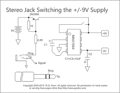
You may want to use the stereo-jack trick to make power switching easier on your stompbox pedals; you'll find that this is not a good idea with a charge pump converter running your -9V supply. This is because in the standard stompbox setup, that wire is the circuit's power *and* signal ground. The current pulses from the switching  converter run on that wire, and will cause the signal ground of your effects circuit to hop up and down at the switching frequency - and you'll hear it!

Simple +9V and -9V from one Battery


Better, wire in the transistor switching circuit shown at left. The stereo jack switches the base drive of a transistor, and that transistor switches the battery into and out of the circuit. The high-current pulses can now go on wires that do NOT share the signal ground, and the whining is avoided.

Basic 200 W power inverter Circuit Diagram


This is the Basic 200 W power inverter Circuit Diagram.This circuit was reverse engineered from a Tripp-Lite "Power-Verter" Model PV200 DC to AC Inverter - typical of those used for camping or boating applications where the only source of power is an auto or marine battery. This particular model is rated 200 W continuous.  The output is a 60 Hz squarewave and there is no regulation or precise frequency control.  (Unlike the other circuits in this collection, it is NOT a high frequency inverter.)


Basic 200 W power inverter Circuit Diagram


Basic 200 W power inverter Circuit Diagram


Modifications for higher or lower output voltage are easily achieved.  For example, a fast cycle strobe requiring 330 VDC, would only require using three times the number of turns on the Output winding and the addition of a bridge rectifier to charge the energy storage capacitor(s).  Alternatively, the inverter could be used as-is with the addition of a voltage tripler.  A tripler rather than doubler is needed because of the squarewave output.  (The RMS and peak voltages are the same so you don't get the boost of 1.414 as you do with the sinusoidal waveform from the power company.)

High power inverter and trigger circuits


I'm building a super strobe bar!   It has 8 strobe tubes under computer control.  (Actually a PIC processor, but hey, computer is a computer.) I have all the stuff done except the control section, and I only have 2 of the 8 strobe units done due to the fact that I haven't found any more cheap cameras at the thrift store! (One Saturday morning's worth of garage sales and flea markets would remedy that! --- sam). It runs on 12 V, at up to 6 A, and can fire the tubes at a rate of about 8-10 times per second.  The storage cap is a 210 uf, 330 V model; it gets to about 250 V to 300 V before firing; depending on how long it has had to charge.

Because of this high speed, the tubes get shall we say, a little warm. (Well, maybe a lot warm --- sam).  I have it set up at the moment driving two alternating 5 W-s tubes.  I'm pumping them quite a bit too hard, as the electrodes start to glow after oh, about 5 seconds or so of continuous use. I know, a high class problem, indeed!  My final assembly will have 8 tubes spaced ut 8 inches apart on a 2x4, with a Plexiglass U-shaped enclosure with a nice 12 V fan blowing air through one end of the channel to cool the inverter and the tubes.  Stay tuned.

 Sourced By: Kevin Horton

Inverter - High power 12 V to 300 V inverter for high repeat rate medium power strobes. Schematic

Inverter - High power 12 V to 300 V inverter for high repeat rate medium power strobes. Schematic


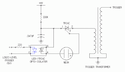
Trigger - Opto-isolated logic level trigger for general strobe applications Schematic

Trigger - Opto-isolated logic level trigger for general strobe applications Schematic